Posted: 8/26/10
Now that the XR10's are starting to hit distributors, we figured that it was a good time to do a step-by-step build of the new kit with pictures and detailed descriptions. This will serve as a guide for a basic XR10 build by the kit instructions. While it is relatively a straight forward build, there are a few steps that require specific screw lengths. It is important that the correct length hardware is used during the build to ensure proper performance.So, let's get started.
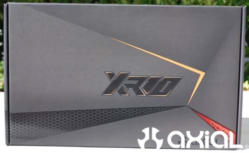
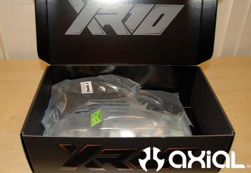
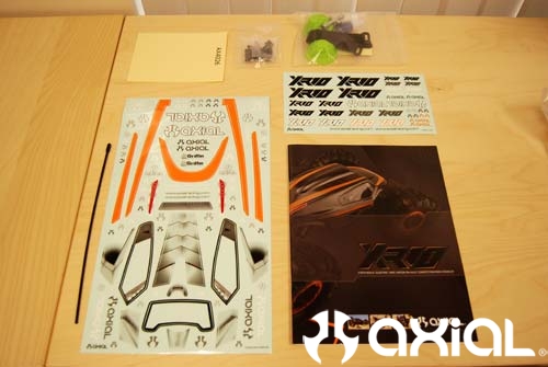
First thing we will do is open that sexy box and take a look inside.
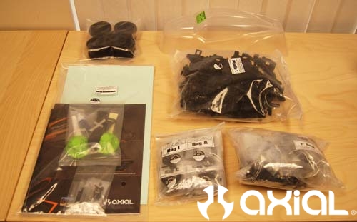
First step involves building the front gear box/axle assembly.
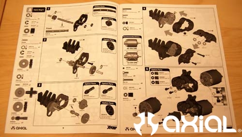
Open up Bag "A" and dump the contents into a small tray or parts catcher of some sort. Each step has it's own bag of hardware, and assorted parts. So, it is very easy to build step by step.
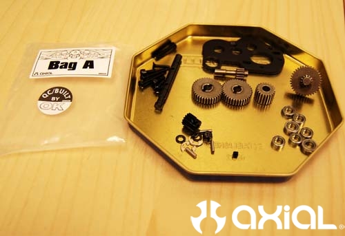
Here you can see all the parts required for step one.
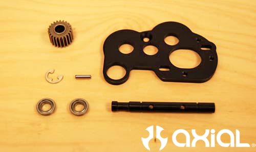
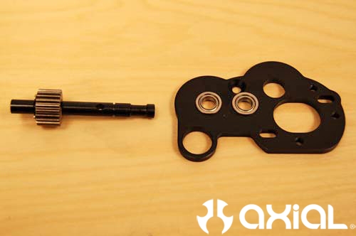
First thing we'll do is set 2 of the flange bearings in the appropriate holes of the motor plate. Then install the drive pin, drive gear and E-clip onto the transfer shaft.
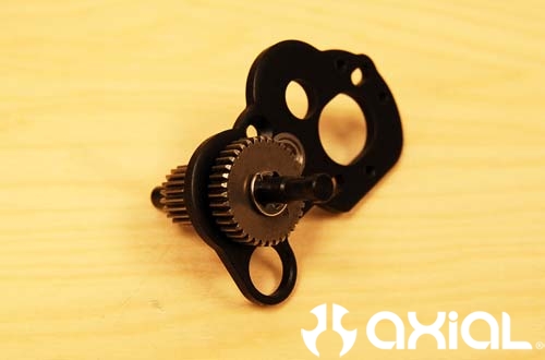
Now slide the transfer shaft through the front bearing and install the drive pin, idler gear and 2nd E-clip.
Grab parts tree #AX80063 and remove part #1, the axle housing's top cap. Install the small 5x8 bearing into the top cap for the transfer shaft. Then, attach the top cap to the motor plate with the supplied flat head screw. After everything is in place, check to make sure the shaft spins freely and the drive gear isn't rubbing anywhere inside the top cap.
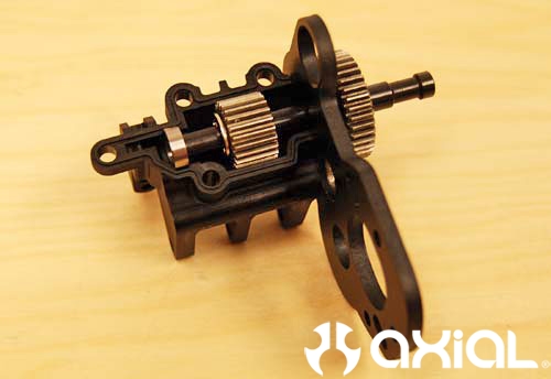
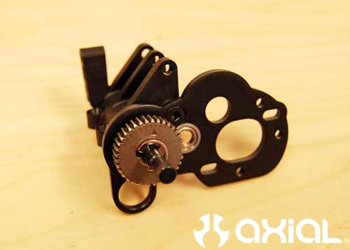
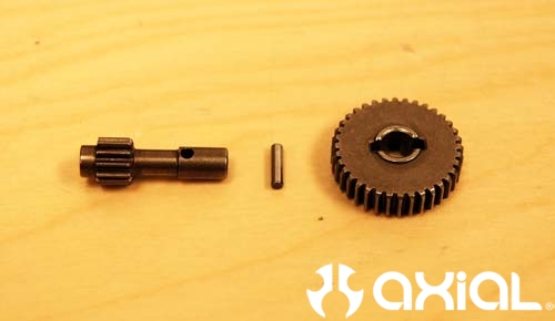
Next, we will install the remaining gears into the gear box. Grab part # AX30556, install the drive pin and idler gear.
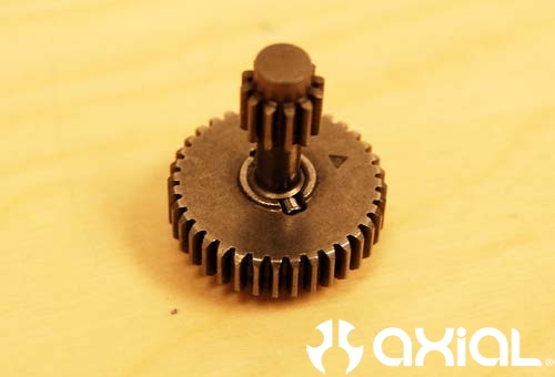
Then, set the assembly into place with the 12 tooth gear towards the flange bearing in the motor plate. Next, install the last flange bearing and stepped gear so the smaller 12t gear is facing away from the motor plate.
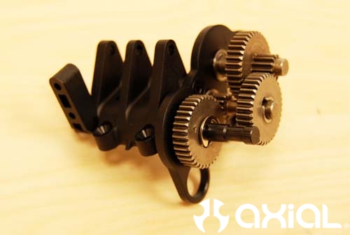
Use the supplied grease in the kit to lube the gears up a little.
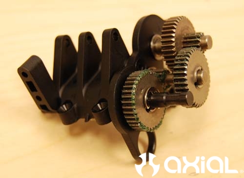
Now you can install the plastic gear case over the whole assembly.
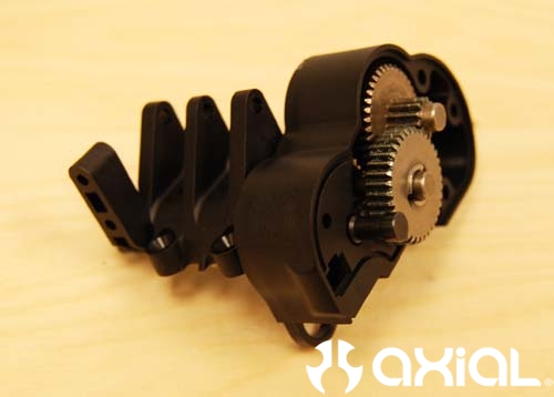
Make sure you install the small M3 Nylock nut into the gear case (see arrow) before moving on to the next step.
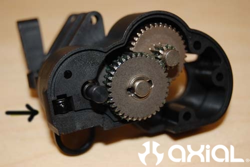
Next, grab the plastic gear case cover and install the three 5x8 bearings.
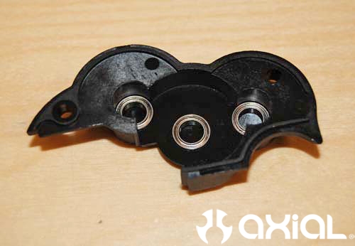
Install the gear cover as shown in the directions.
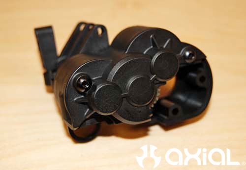
Grab the front axle housing, specifically the top half. Set the gear box into place, and attach with the supplied hardware. Be careful with this step, it is important that the correct screws go into the correct hole. If too long of screw is used you run the risk of pinching the bearings on either side of the spool gear. This will put tremendous strain on the whole front axle, causing binding at the bare minimum.

For the next step we will install the bearings onto both sides of the spool gear, and grease the gear up before dropping it into place in the axle housing. Pay close attention to the spool gear's orientation in the axle housing too, it isn't symmetrical on both sides.
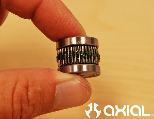
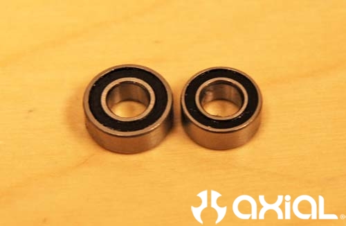
Now install the outer bearings into the axle tubes. Pay close attention to this step too. There are 3 different size bearings in Bag "B". You want to install the smaller 5x10 bearings in the axle tubes. The slightly bigger 5x11 bearings are for the steering knuckles. Here you can see the slight size difference in the 2 bearings.
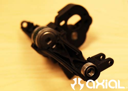
Grab the bottom half of the front axle housing and install the steering slider, again pay attention to the orientation.
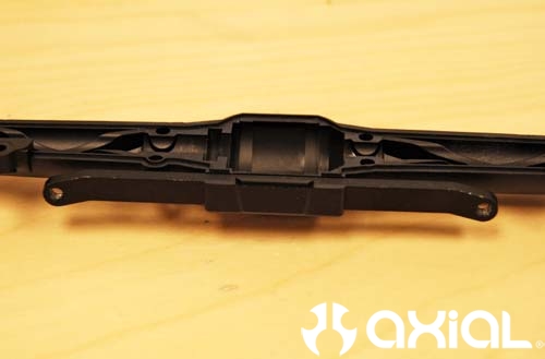
Next assemble the 2 halves of the axle housing and tighten everything up.
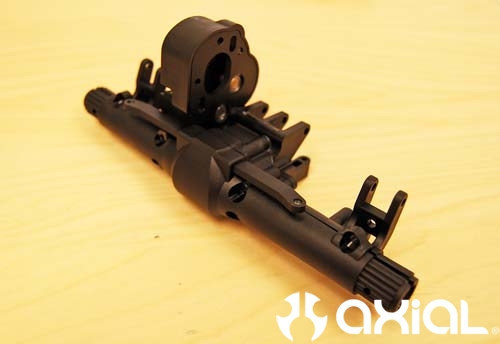
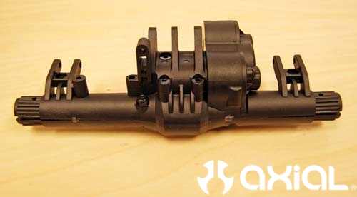
Now it's time to install the C hubs and steering servo mount. Here you can see all the parts required for this step.
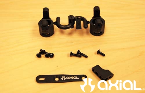
Slide the C hubs onto the ends of the axle tubes, note the orientation on these as well. The longer ear will go towards the bottom of the axle housing. Use the supplied short self tapping screws to attach the C's to the housing. Then, attach the plastic servo mount to the aluminum servo plate using the self tapping button head screw. Then use the flat head screws to tie the servo mount to the axle housing.
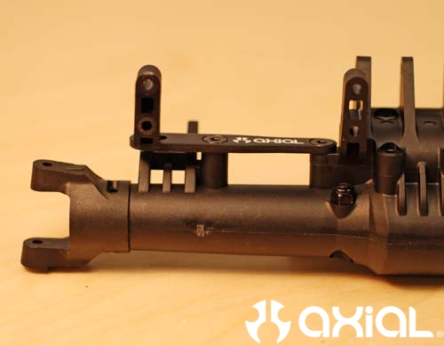
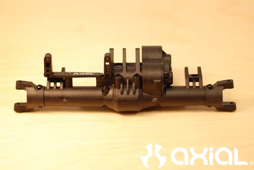
Here is what the front axle will look like when you are done with this step.
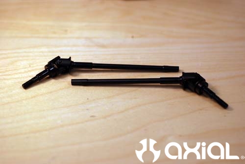
Moving on to the knuckles and inner axles. Here you can see the new oversize universals for the front axle.
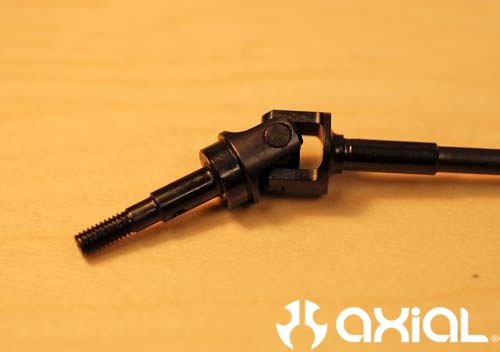
A closer look at the U-joint.
Time to prep the steering knuckles for installation on the axle.

Drop the bearings into place on the backside of the knuckles.
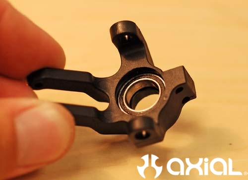
Install the 5x11 bearing into the front of the knuckle, and screw the steer arm onto the passenger side knuckle.
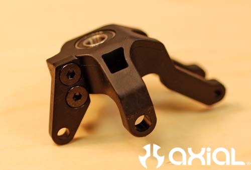
Now grab the knuckles, flange pipes and 3x10 button head screws to install the knuckles.
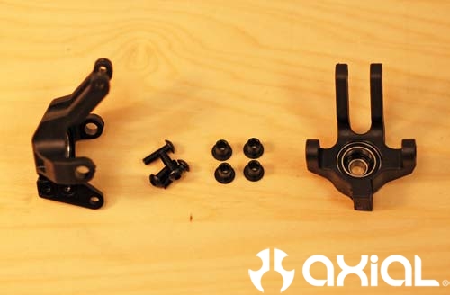
Install the universal axles into the axle housing first. Then insert the flange pipes into the knuckles, slide the knuckles over the universals and onto the C hubs. Use the 3x10 screws to secure the knuckles to the C's. Now check and make sure you aren't getting any bind, the knuckles should move freely. Otherwise your servo will have to work even harder then normal.
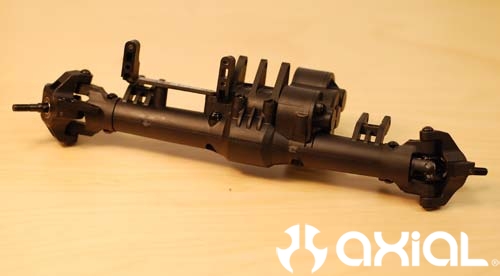
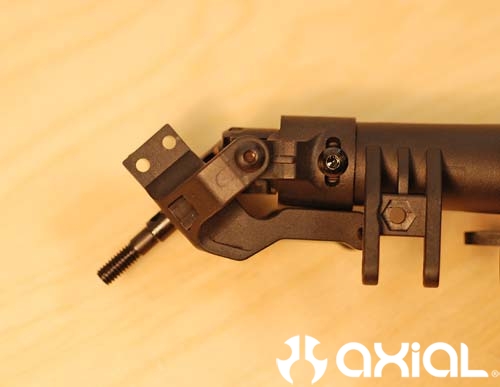
Now on to the steering turnbuckles.
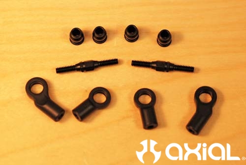
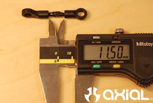
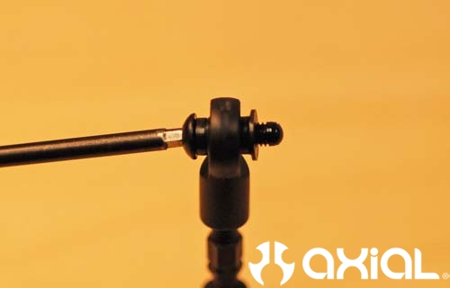
Thread the rod ends onto the turnbuckles, take note that one side has a right handed thread and the other a left handed thread. So, one rod end will thread on clockwise, the other will be counter clockwise. Thread the rod ends on until you have an 11.5mm (or .453 for those anti metric countries like us) gap between the ends. Using turnbuckles like this allows you to change toe in/toe out on the fly.
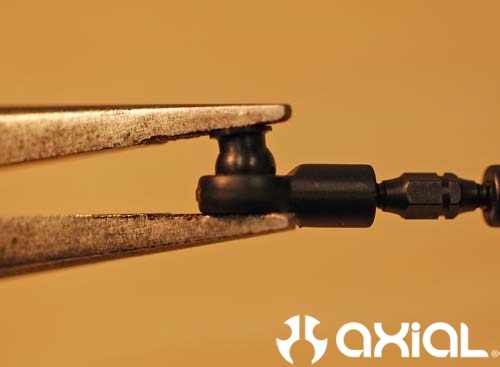
Pop the flange balls into the rod ends with a pair of pliers, note the direction of these too as you assemble.
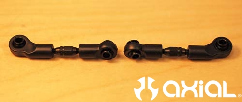
Here you can see both turnbuckles side by side. Notice the groove cut into the hex on the turnbuckle, make sure they are facing the same rod end for both sides.
Install the turnbuckles onto the front axle as instructed, and use thread lock on the steering slide to avoid any lost screws while out in the rocks.
The complete weight of the stock front axle is 8.7 ounces.
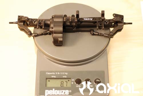
That wraps it up for the front axle. Stay tuned for the next installment on assembling the rear axle.