Posted: 10/5/11
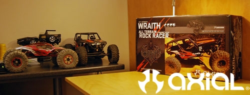
Now that the Wraith kits are hitting hobby shops, we figured it would be a perfect time for another step by step build. I recently built up one of these kits and took photos of each and every step. Over the next few days you will see this build progress, step by step, with photos and descriptions. I will also show a few different option/upgrade parts as well with this particular build. For the first step in this build we will go over what's inside the box, then start with the construction of the axles.Prepping my desk for the build.
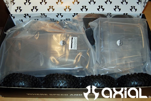
A peak inside the box shows all the goodies!
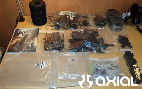
Here you can see the contents of the kit laid out.
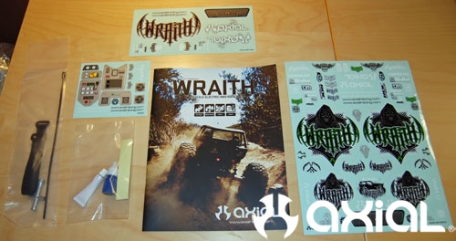
The decals and instruction manual.
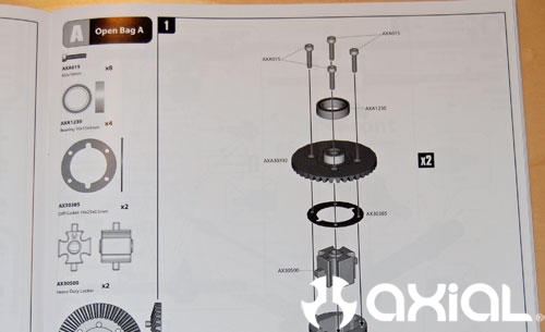
Step 1 in the manual says locate bag A.
Find the hardware bag, which contains all the metal parts required for this build. Open it up and look for bag A.
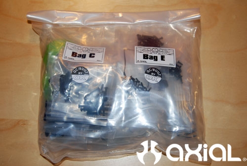
Bag A located.
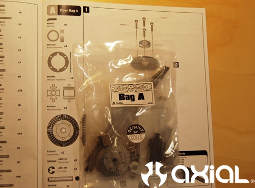
Bag A's contents.
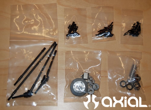
Here are all the parts required to build both differentials.
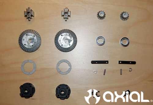
Start off with what you need to build the first ring gear assembly.

First thing we'll do is install the locker in the plastic differential case, and place the differential gasket over the ring gear.
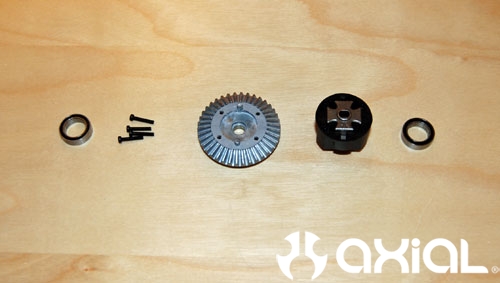
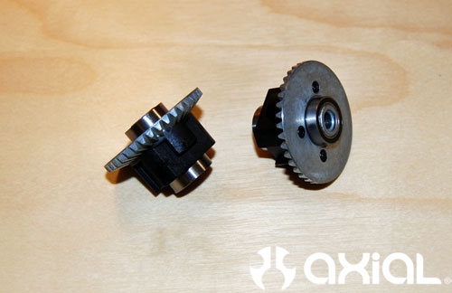
Now mate the differential case to the ring gear and attach using the supplied 2mm screws. Then slide the bearings over the bosses on each side of the differential. Repeat these steps for both assemblies.
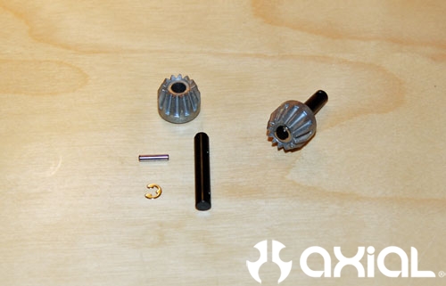
Assembling the pinion gear is next. Insert the 2mm pin through the pinion shaft hole closest to the end of the shaft with the E-clip groove cut into it, and slide the pinion gear into place over the pin. Then snap the E-clip into place with a pair of needle nose pliers.
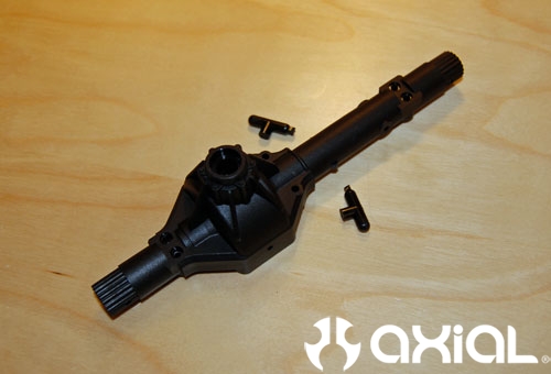
Locate the AR60 axle housings and snap the plastic tabs off.
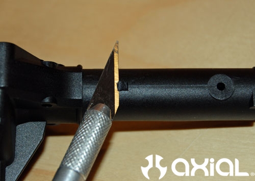
Trim any excess plastic away from the housing with an X-acto.
Find the differential cover parts tree.
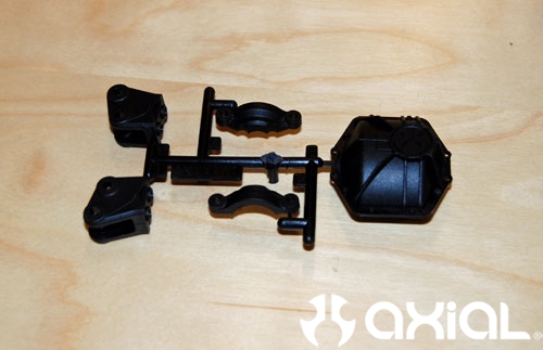
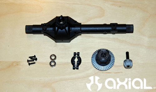
Here are all the parts required for step 2.
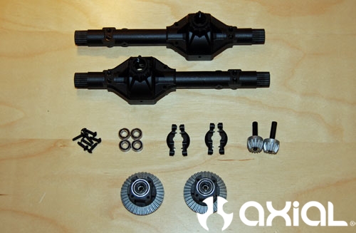
Start with the first housing and the parts needed for assembly.
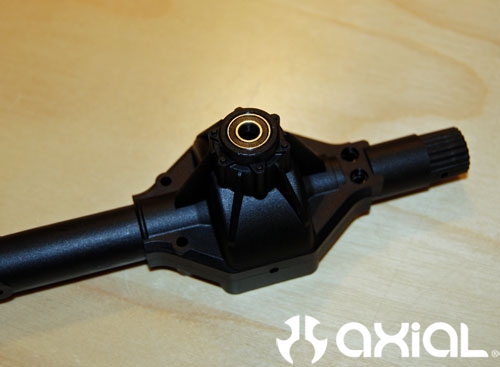
Insert the first 5x11 bearing into the backside of the AR60 housing.
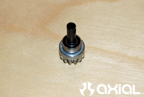
Slide the 2nd 5x11 bearing into place on the pinion shaft.
Press the pinion gear into the housing.
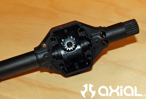
Insert the differential assembly into the housing next. Make sure you note the direction the ring gear is suppose to be facing too. The teeth of the ring gear should be facing the short side of the housing for the front axle.
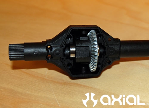
Install the bearing caps with the supplied self tapping screws.
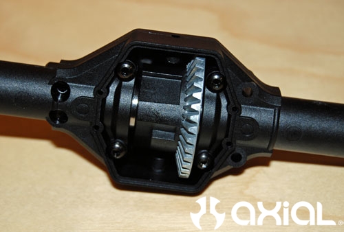
Apply a little grease to the ring and pinion gears. Don't go overboard with the grease either, a light coat that fully covers the gears is more then enough.
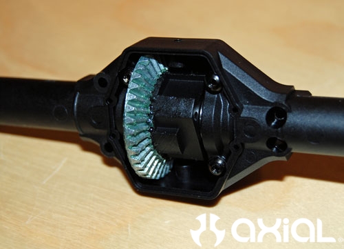
Grab your differential cover and four 2mm screws.
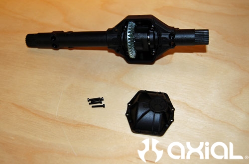
Install the diff cover with the supplied hardware. Also note the direction of the diff cover placement too.
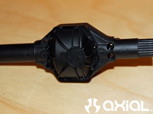
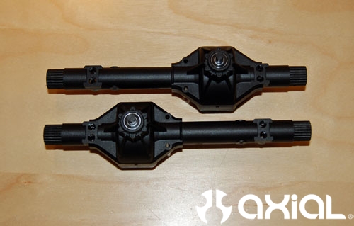
Now repeat the above steps for the rear axle. Again note the direction of the ring gear, the teeth should be facing the long side axle tube for the rear axle. This would be a good time to mark the axles so you know which one is for the front and rear. I marked the front axle with an "F" underneath the differential on the outside of the housing with a marker. Otherwise it's easy to get the 2 axles confused during the build.
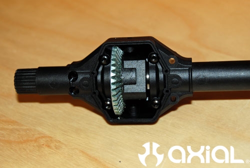
That completes step 2.
For step 3 I will be adding a few option parts, like aluminum C-hubs, knuckles and 3x10mm M3 screws, instead of the self tapping plastic screws. When you upgrade to the aluminum C-hubs the self tapping screws can no longer be used, since the C's are tapped for M3 hardware.
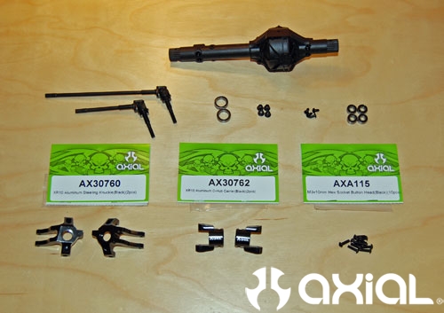
Slide the axle C's into place, again note the direction in the manual.
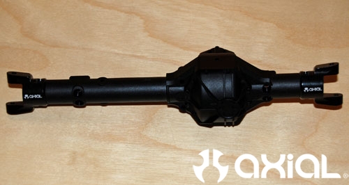
Insert the self tapping screws into the C-hubs.
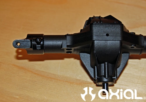
Install the 5x11 bearings into the ends of the axle tubes.
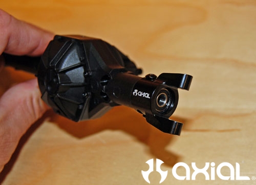
Next step may seem off, but squirt a dab of Loctite on the flats of the axle shafts before installing them in the housing. This is done to minimize the slop between the locker and axle shafts.
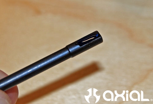
Slide the CVD axles into place.
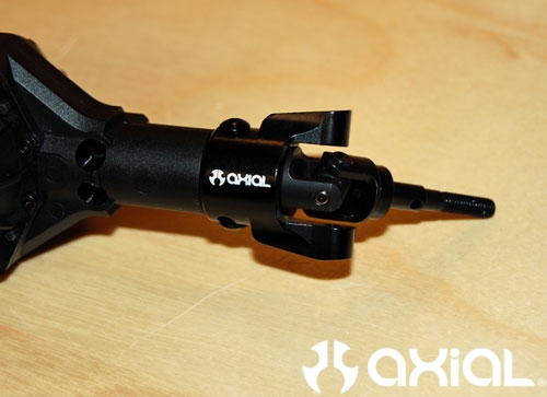
Now it's time to prep the aluminum knuckles.
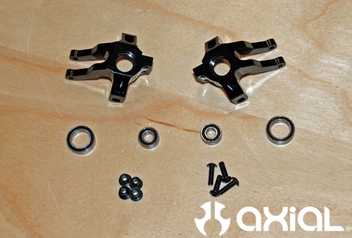
Install the required bearings.
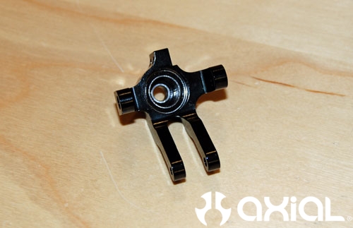
Insert the flange pipes into the knuckles, slide the knuckles over the outer stub axles and install the 3x10mm M3 screws.
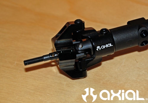
Repeat the last few steps for the opposite side of the front axle. and Step 3 is done.
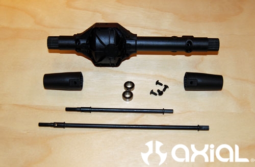
Onto the rear housing, everything needed laid out for ease of assembly.
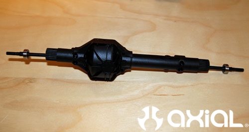
Again add a dab of Loctite to the axle shaft flats before installing them. Slide the two 5x11 bearings into place and insert the rear straight axles into the housing.
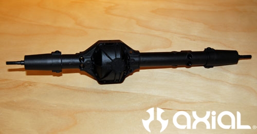
Slide the plastic lockouts into place and attach using the supplied hardware.
Moving on to step 5, and the front axle. First thing I did was install the M3 set screws into the bottom of the axle housing.
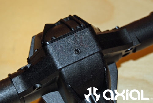
Grab the proper plastic axle truss and set it into place on top of the front housing.
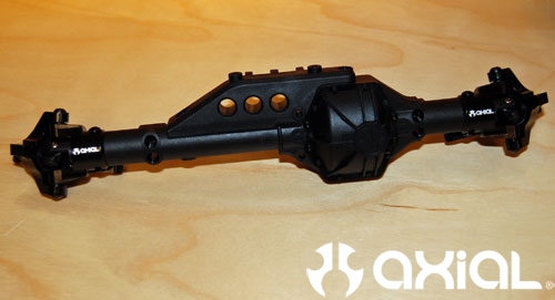
Attach the truss with the supplied hardware.
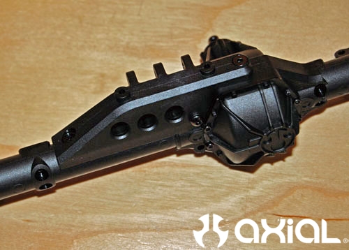
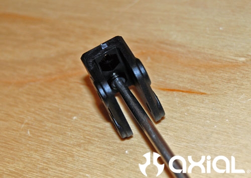
Next we will attach the link/shock mounts. For this step I found the best way to get the Nylock nuts seated into the link/shock mounts was to use a small pick tool. Slide the Nylock nut onto the end of the pick, insert the nut into the link/shock mount, then twist and pull the pick out. The nut should stay seated in place.
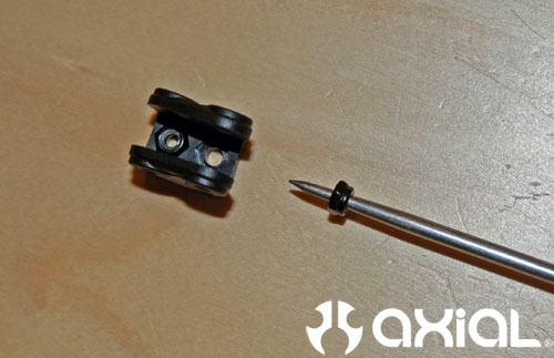
Attach the link/shock mounts with the supplied M3X16mm screws. Note the direction of these as well, they can be bolted on upside down by accident with ease.
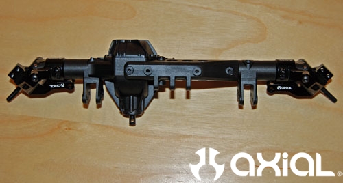
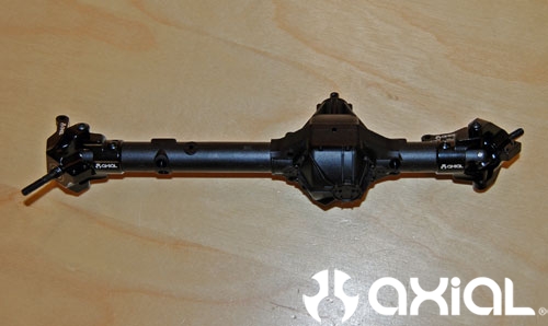
Repeat the last couple steps to finish off the rear axle. Both axles completed.
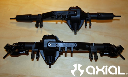
That takes care of the first few steps in this build covering the axles. Next step will be shock build up and tuning.
Axial Wraith Kit Build Series
Step 2
Step 3
Step 4
Step 5
Step 6
Step 7