Posted: 9/26/12
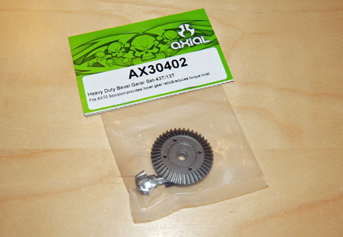
Here is the final installment of my Ridgecrest crawler build, Stage 3. For this stage of the build I will be adding AR60 universals, aluminum shocks, under drive ring and pinion for rear axle, aluminum c-hubs, aluminum knuckles, aluminum lockouts, HD motor plate and a 55t motor. I will also be adding a few hop-ups from Vanquish Products as well. If you have never heard of Vanquish Products, check them out!! Their machine work and quality control is second to none. I will be adding a set of their DH wheels and titanium steering links to this build. So, let's get started!!The first hop-up I started with is the under drive ring and pinion for the rear axle. Adding the slower gear set to the rear axle will keep the front axle spinning faster in all situations. This will help with tight turns, and getting the front tires to pull up steep ledges. It can also help alleviate torque twist/chassis roll while on the throttle, which all shaft driven crawlers suffer from. The difference in the gearing between the front and rear after this modification is very slight, but it makes a pretty big difference. The old ring and pinion had a 13t pinion, with a 38t ring gear. This HD under drive combo has a 13t pinion and a 43t ring gear. It may sound like a big difference, but it really isn't. Original ratio was 2.92:1. The new ratio for the rear axle is 3.30:1.
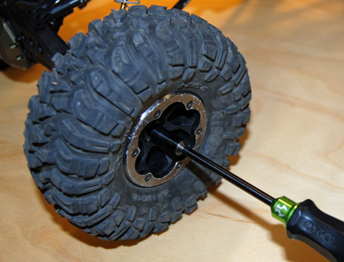
Since I will be tearing into both axles, I started by removing all 4 tires with my 7mm driver.
After removing the tires use a 1.5mm driver to remove the drive hexes and cross pins.
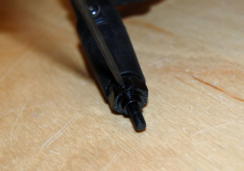
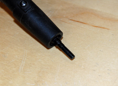
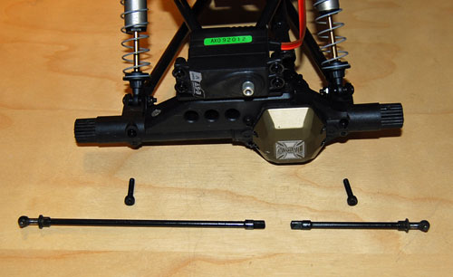
Now we can remove the two screws that hold the rear axle lockouts in place. Slide the lockouts off the housing, and just let them hang there for now.
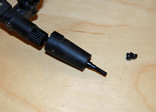
Then loosen the driveshaft set screw at the rear axle housing, and set the male half of the driveshaft aside for now.
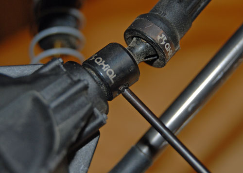
Next we can pull the differential cover off to access the ring and pinion.
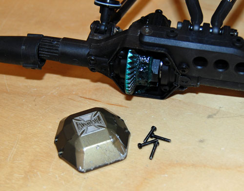
Now remove the plastic bearing retainers using a 2mm driver.
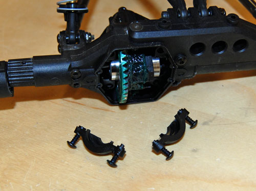
Make sure the axle shafts are pulled out of the differential assembly. Then you can remove the differential. I used a paper towel to wipe most of the grease away, makes working on the assembly a lot easier.
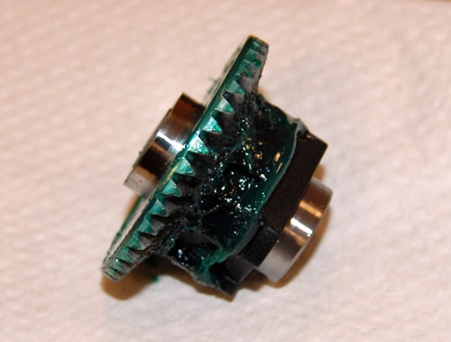
Remove the 4 screws holding the ring gear to the plastic diff housing. Pull the bearing off the ring gear as well.
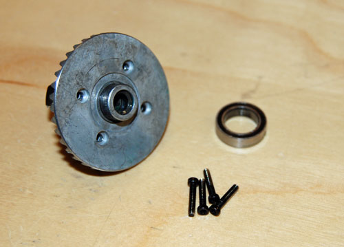
Now pull the ring gear off the diff housing. Be careful not to rip the gasket that goes in between the gear and housing. You will want to re-use those with the new ring gear.
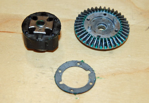
Set the gasket into place on the new ring gear so the hole pattern lines up.
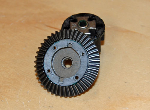
Now you can re-assemble the differential, and slide the bearing into place on the new ring gear.
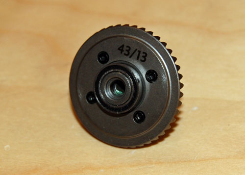
Slide the old pinion gear out of the axle housing.
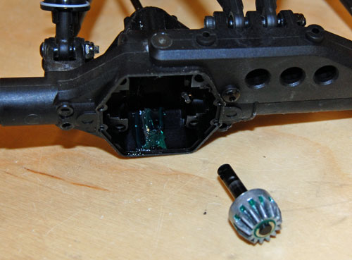
Now slide the new HD pinion into the axle housing. Double check that both bearings are still in place at this time too.
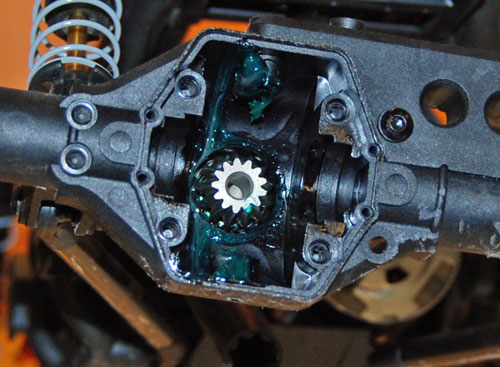
Set the differential assembly into place, after applying a light coat of grease to the ring gear.
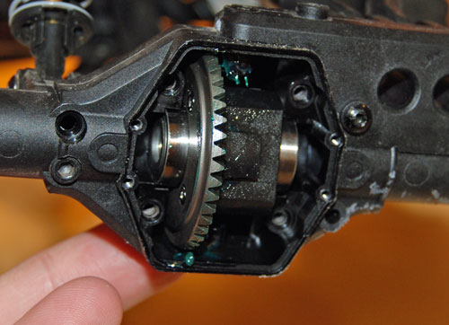
Re-install the plastic bearing retainers.
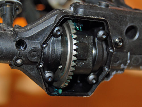
Slide the axle shafts back into the differential assembly. Notice I also installed some aluminum lockouts at this time too.
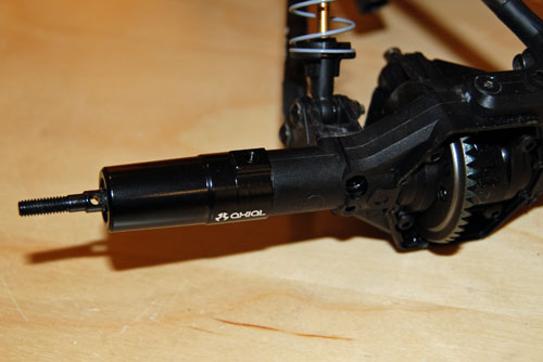
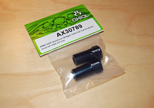
Next I will install a 55t motor for more torque and better low speed throttle resolution. I will be running this with a small 3S lipo, I have some older 1550mah packs that should work perfect.
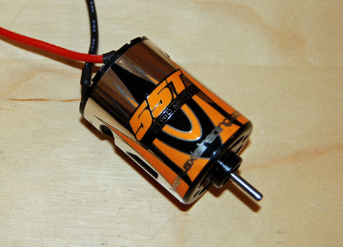
Start by unplugging the stock motor from the ESC.
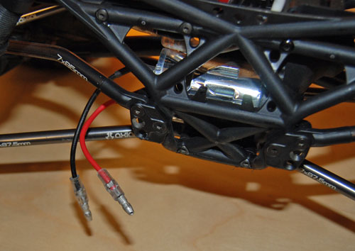
Then remove both set screws that hold the driveshafts to the transmission outputs.
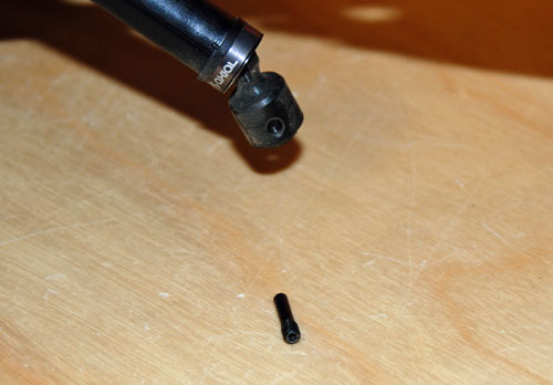
Remove the four screws that hold the battery tray in place. Remember that I moved the battery tray from the back to the front during Stage 1.
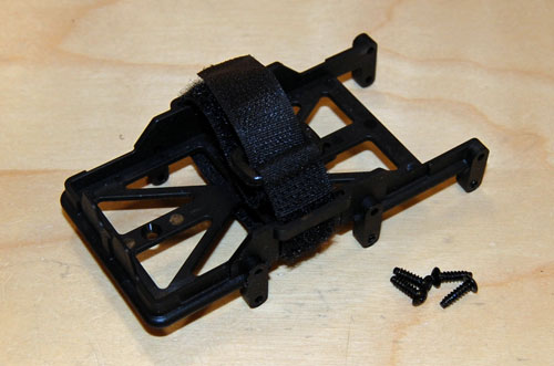
Lay the chassis on it's side and remove the four screws that hold the transmission into place.
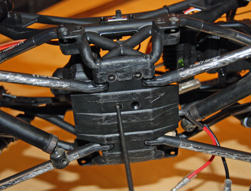
With the transmission out of the chassis, you can remove the spur gear cover to access the motor mount screws.
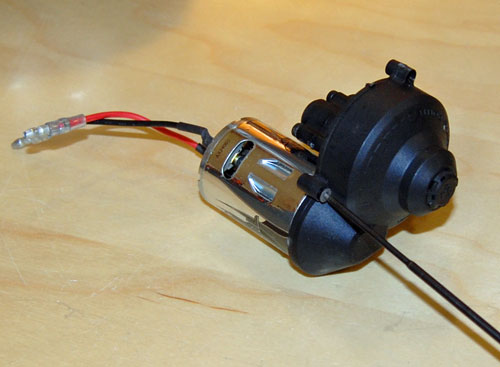
Using a 2.5mm driver remove the motor mount screws.
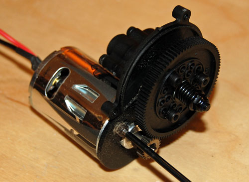
Remove the motor from the transmission.
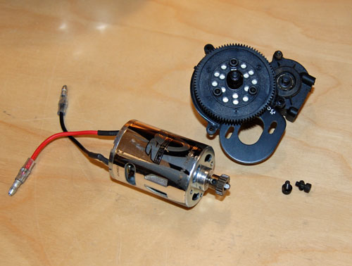
Now we can pull the pinion off the motor's output shaft.
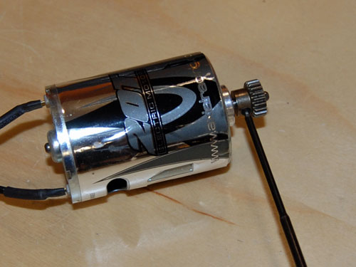
While I have the transmission out on the bench I am going to swap the stock motor plate for our new HD motor plate. The newer plate has integrated heatsinks machined into it to help dissipate heat.
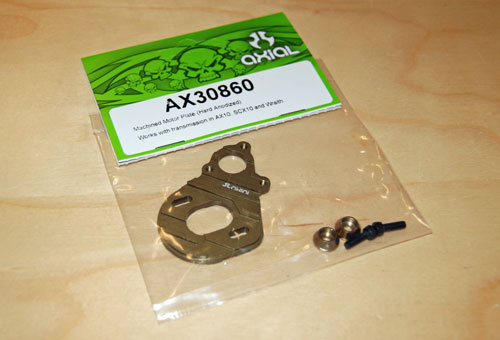
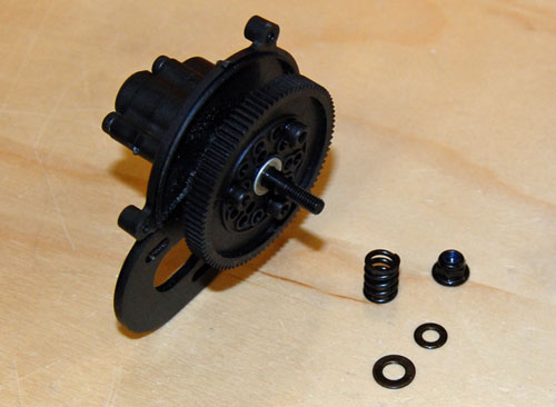
In order to install the new motor plate we will have to remove the slipper clutch/spur gear assembly. Using a 7mm nut driver remove the slipper nut, spring and washers.
Slide the spur gear off the shaft, and remove the drive pin.
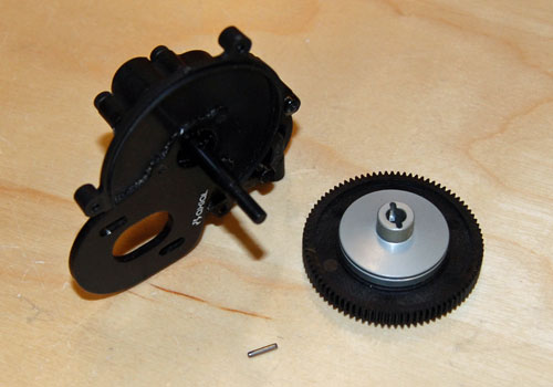
Using a 2.5mm driver remove the motor plate from the transmission.
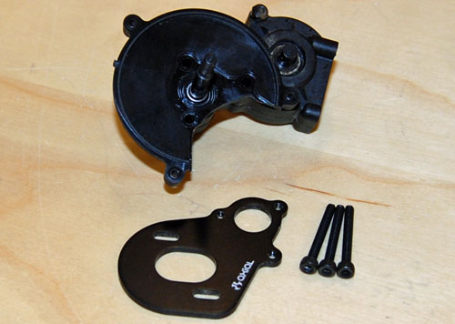
Set the new motor plate in place and attach with the existing 3mm screws.
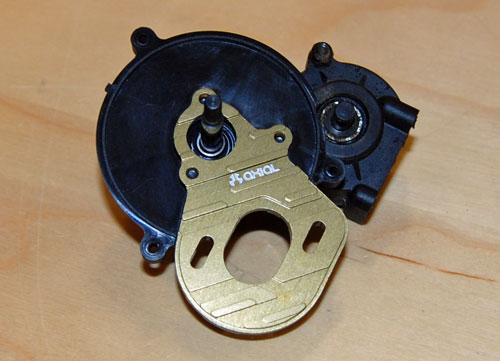
Next we can bolt the spur gear assembly back into place, don't forget to install the cross pin first.
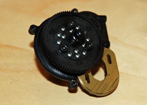
Now we can install the new 55t motor. I already installed the pinion gear onto the motor shaft. We just need to set the proper gear mesh and tighten everything down. The easiest way to set gear mesh is by inserting a small piece of paper between the spur gear and the pinion gear. Hold the two gears together with the paper in between and tighten your motor mount screws. Remove the paper and you should have a little bit of play between the two gears, which means you are good to go.
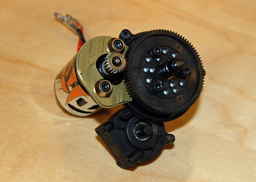
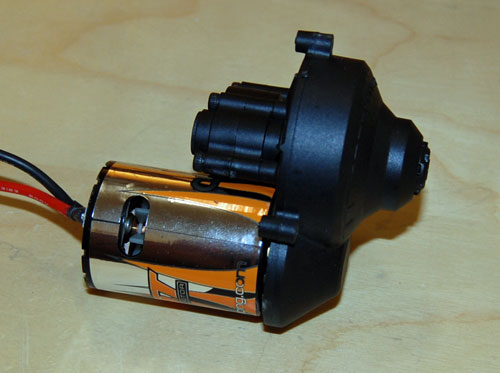
Re-install the spur gear cover next. Now you can bolt the transmission back into the chassis, and re-attach the driveshafts.
Next I will be swapping out the stock plastic shocks for our aluminum competition shocks. The aluminum shocks have a lot more consistent feel to them, and are smooth as silk when properly built.
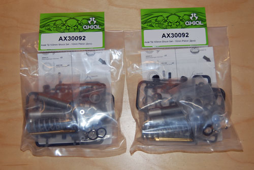
Here is a link that will give you some tips for proper build up of our competition shocks.
https://www.axialadventure.com/blog_posts/1132
A shot of the freshly assembled shocks.
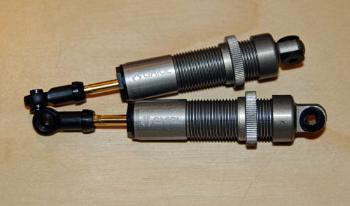
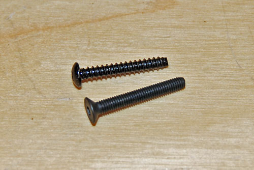
One change I made here was to use the rubber bushings that come with the new aluminum shocks in the shock cap, instead of the plastic ball studs. In order to keep the bushings in good working order, and free to move back and forth a little, I swapped the self tapping plastic screws for machined M3 flathead screws. The finer threads on the M3 screw shouldn't tear the upper shock bushing like the stock self tapper would over time. I also went with a flathead screw over a buttonhead to let the upper shock cap pivot better as the suspension cycles.
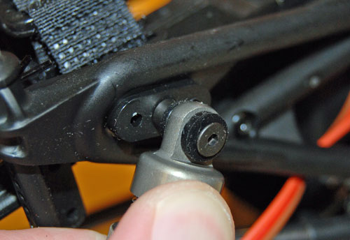
All installed and ready to go!
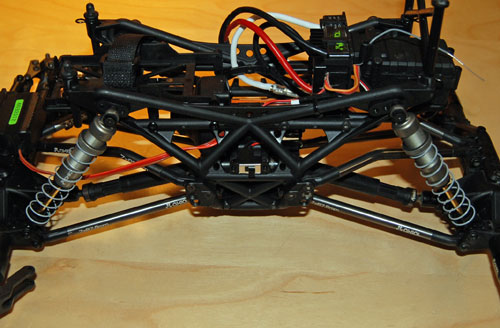
Next we will address the front axle. I am going to install AR60 universals, aluminum c-hubs, aluminum knuckles and Vanquish Products titanium steering links.
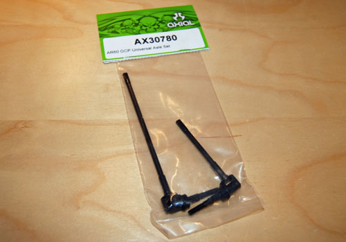
Universals.
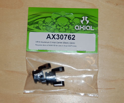
C-hubs.
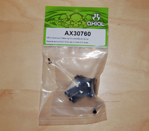
Knuckles.
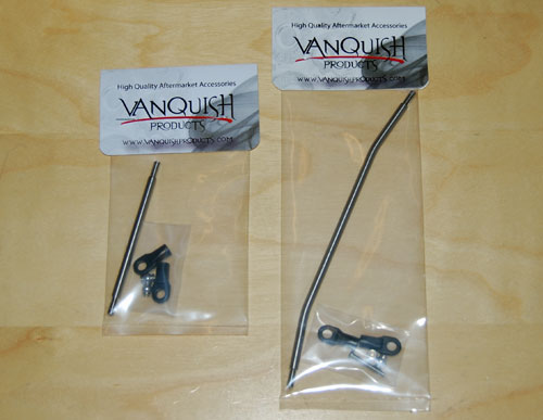
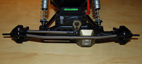
Vanquish steering links.
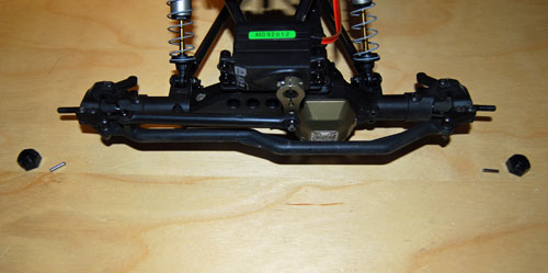
Start by removing the drive hexes and cross pins.
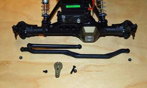
Then remove the servo horn and steering linkage.
Remove the four screws that hold the c-hub and knuckle assembly on the axle housing.
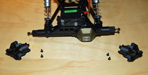
Next we need to remove the inner axles. But, to get them out of the housing you will need to remove one screw from each lower shock/link mount. Removing those will allow the flange on the inner axles to slide out with out hanging up on the link mount screws.
Slide the new aluminum c-hubs into place. I clocked them back just a little to help with tight turns. Make sure the c-hubs are oriented correctly, the longer ear on the hubs should be on the bottom of the axle.
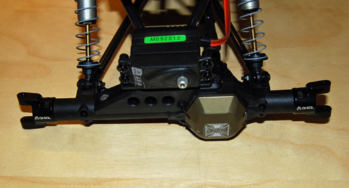
Here you can see they are slightly clocked, but not to the most extreme point.
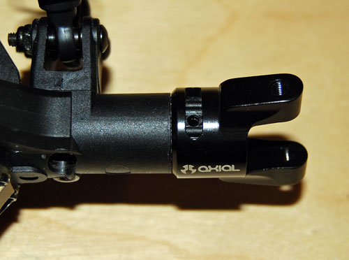
Install the c-hub screws top and bottom for both sides.
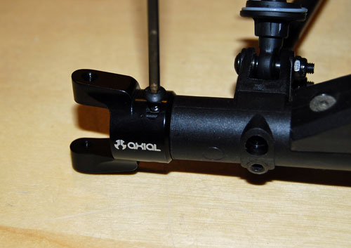
Grab the universals next.
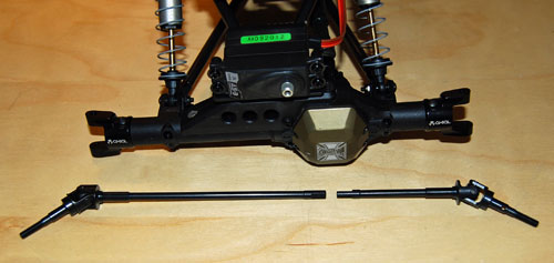
Slide the universals into the housing and seat them into the diff assembly.
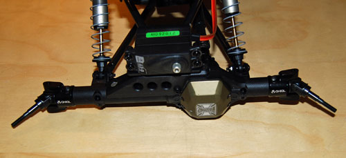
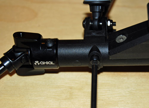
Now you can re-install the two screws we removed from the lower link mounts to get the stock inner axles out of the housing.
You will need the bearings, king pin sleeves and kingpin screws from the old knuckle/c-hub assembly. So, pull them apart and grab what you need to build the new knuckles up and bolt them into place on the c-hubs.
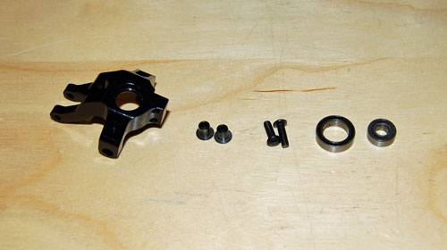
If you are struggling with installing the new bearings, use the old outer axle to line them up properly and press them into place.
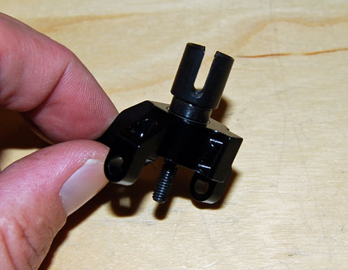
Install the kingpin sleeves into the new knuckles and slide them over the c-hubs. Make sure the kingpins sleeves stay in place.
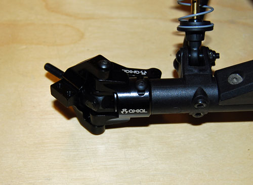
You will need to replace the old self tapping knuckle screws with 10mm long machined M3 screws. The stock knuckles were held in place by plastic self tapping screws, but you can't use those screws in the new c-hubs as the hubs have a machined M3 thread in them. So, you will need some M3X10MM machined screws to complete this step. Part number for those is AXA115. There are 10 screws per package, so one pack is enough to do the job.
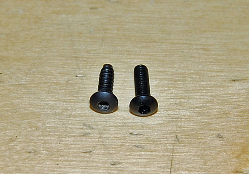
Next we need to bolt the tie rod arms onto the knuckles. But, you will need to swap the stock plastic self tappers for machined screws again. Luckily they are the same length as the kingpin screws from the previous step, and you will have some leftover to use here as well.
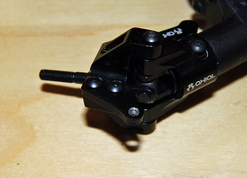
Now we will assemble the Vanquish tie rod and drag link. Pretty straight forward, thread the rod ends onto the linkage and pop the ball studs into place. You will have to fine tune the lengths of both the tie rod and the drag link once they are bolted up, in order to ensure the tires are straight and the servo horn has even throw to both sides.
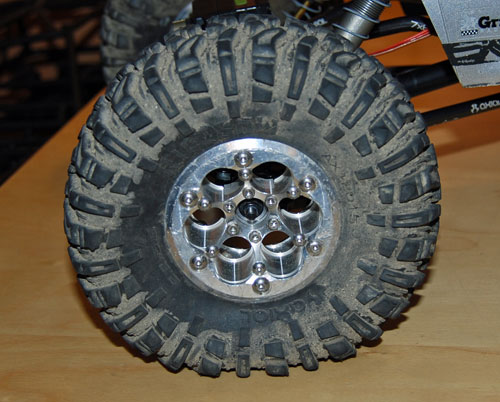
Next I installed my Vanquish DH comp wheels. They are machined aluminum, and the weight of them alone should be sufficient in most situations. If I find the front is too light I will add some weighted slugs to the front wheels.
A few finished shots of this rig as it sits now.
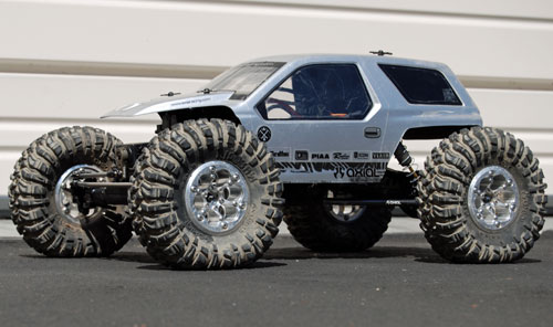
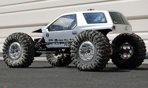
Mandatory flex shots.
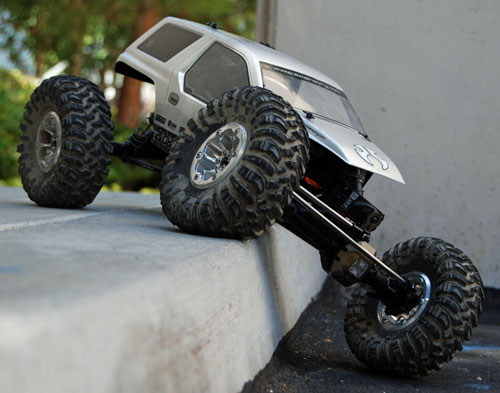
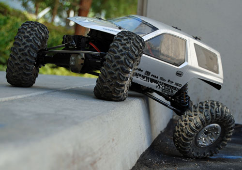
That wraps up Stage 3 of this Ridgecrest crawler build. I am going to try and shoot some video of this stage too, just to see/show the difference in performance over Stage 2. Stay tuned!!
Link - Stage One Ridgecrest Build
Link - Stage Two Ridgecrest Build
Parts list for the three stages of this build.
Stage one
AX30223 Black competition springs (x2)
Stage two
AXA1331 Steel ball studs (x5)
AX30836 Aluminum 25 spline servo horn
AX30829 Aluminum differential cover (x2)
AX30797 Aluminum link kit
AX12015 R35 Ripsaw tires (x2)
AX08061 XR10 beadlock wheels
Vanquish wheel weights
Stage three
AX30402 HD 43/13 ring and pinion gears (rear axle only)
AX30789 Aluminum rear axle lockouts
AX24007 55t motor
AX30860 HD motor plate
AX30092 Aluminum comp shocks (x2)
AX30780 AR60 CVD's
AX30762 Aluminum c-hubs
AX30760 Aluminum knuckles
VPS03122 Vanquish titanium drag link
VPS03110 Vanquish titanium tie rod
Vanquish 2.2 Aluminum wheels
Vanquish wheel weights (x2)