Posted: 11/27/18

Our AX90046 build series continues and up until now, it's been assembling sections of the rig, but when we've finished, it still looks like a pile of parts. Well, in this blog entry, the build is really going to start to take shape. Here we're going to assembly the chassis and start bolting on all of those sections from the previous steps. Let's make this pile of parts look like a rig!
STEP 1
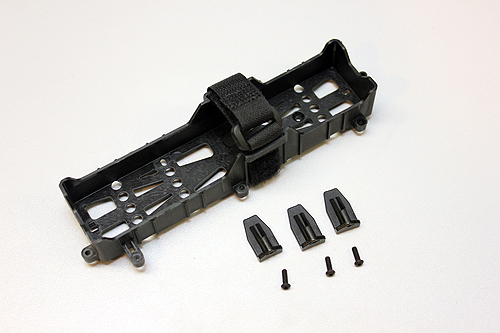
First we turn our attention to the battery tray. The Velcro strap needs to slipped into the tray with the fuzzy side facing out. This will allow the hook of the velcro to secure to the loop. While the tray is out, you should install the battery position tabs in the tray. This is often left out, but if all of your packs are the same, its a good idea to use these so your battery doesn't shift.
STEP 2
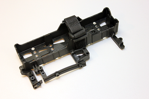
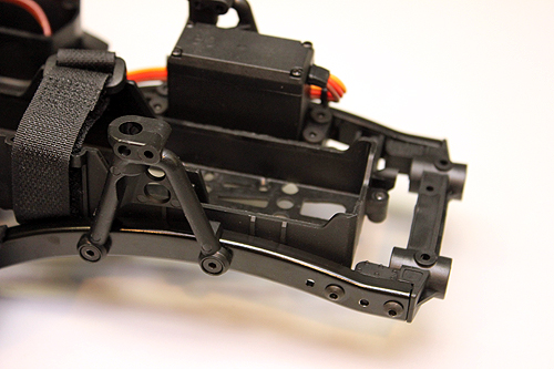
Next up, install the servo mount and brackets. No real tips here, just make sure you don't overtighten the screws and strip out any holes.
STEP 3
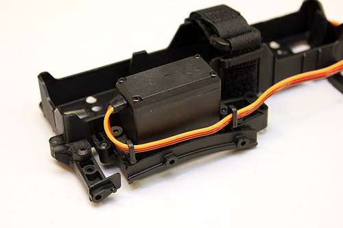
The servo goes in next with the splined output facing forward. Don't forget to use the sire wire security strap/ tabs which makes wire routing much cleaner.
STEP 4
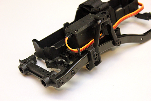
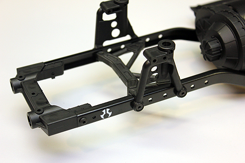
The front tower goes on next. The tower with the panhard bar mount is used here. Pay extra attention to the size of the hardware used.
STEP 5
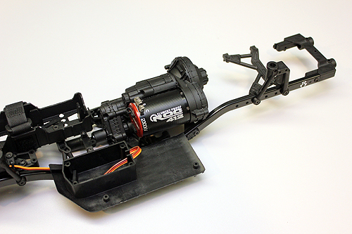
Lots going on in this step. Start by installing the side tray on the chassis, but before doing so, take special note that the servo lead wire is run between the tray and frame rail for a nice clean look. The screws for the tray also secure the transmission to the frame rails. After the tray is in, install the correct rear shock tower and then the cross members. Pay attention to the frame holes the tower is postioned in. This corresonds with the proper wheelbase for this build.
STEP 6
Now the opposite side frame rail is installed. Start securing the rail by screwing the shock tower into position.
STEP 7
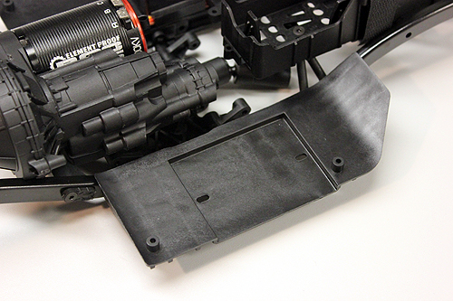
The tray goes into position next. The hardware will secure the tray to the frame and in turn secure the transmission.
STEP 8
Time to button up the rest of the chassis assembly by installing the front tower and front bumper mount screws.
STEP 9
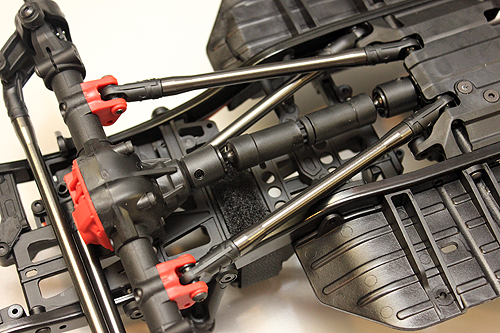
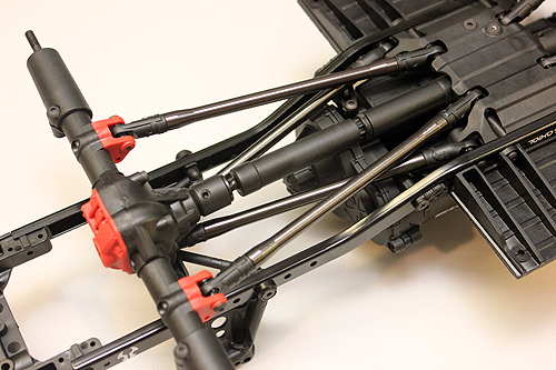
The assembly is really getting interesting now! Take your front axle and link assembly and start attaching it to the chassis by inserting the center Wild Boar Driveshaft to the axle output and install the retaining screw-pin. With the driveshaft in place, you can screw the links to the chassis.
STEP 10
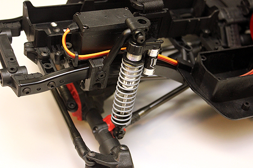
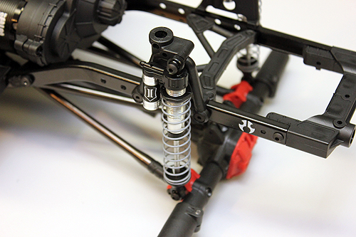
Next, the shocks are installed onto the shock towers and lower brackets. Make sure you use the front shock assemblies here. Don't overtighten the shock mounting screws. Overtightening can pinch the plastic ball studs.
STEP 11
Here is a tricky part. Installing the servo horn. If you went ahead and screwed the panhard bar to the mount, it might be easier to get the horn onto the servo by removing the panhard link. With it out of the way, install the servo arm on the steering link and secure the horn to the servo. We know you already centered your servo before installing it... right?
STEP 12
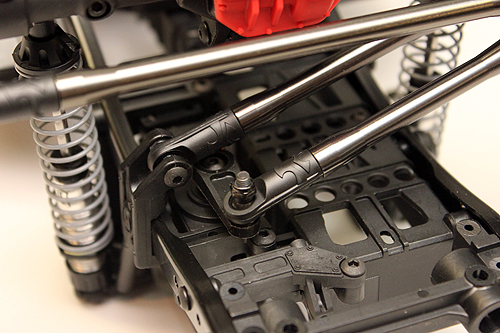
Just like the front, the rear axle and link assembly gets bolted to the frame. Remember to install the driveshaft first before attaching the links to the chassis.
STEP 13
Bolt the rear shocks to the towers and axle brackets.
FINISHED
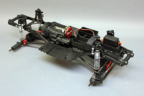
Now it's starting to look like an SCX10II.